The stepper motor:
An important choice in CNC machines' design is the appropriate motor to use, at the moment I'm designing a small milling machine and I plan to use steppers type NEMA 17 for it, you can find their datasheet here.
For now I'm using this stepper:
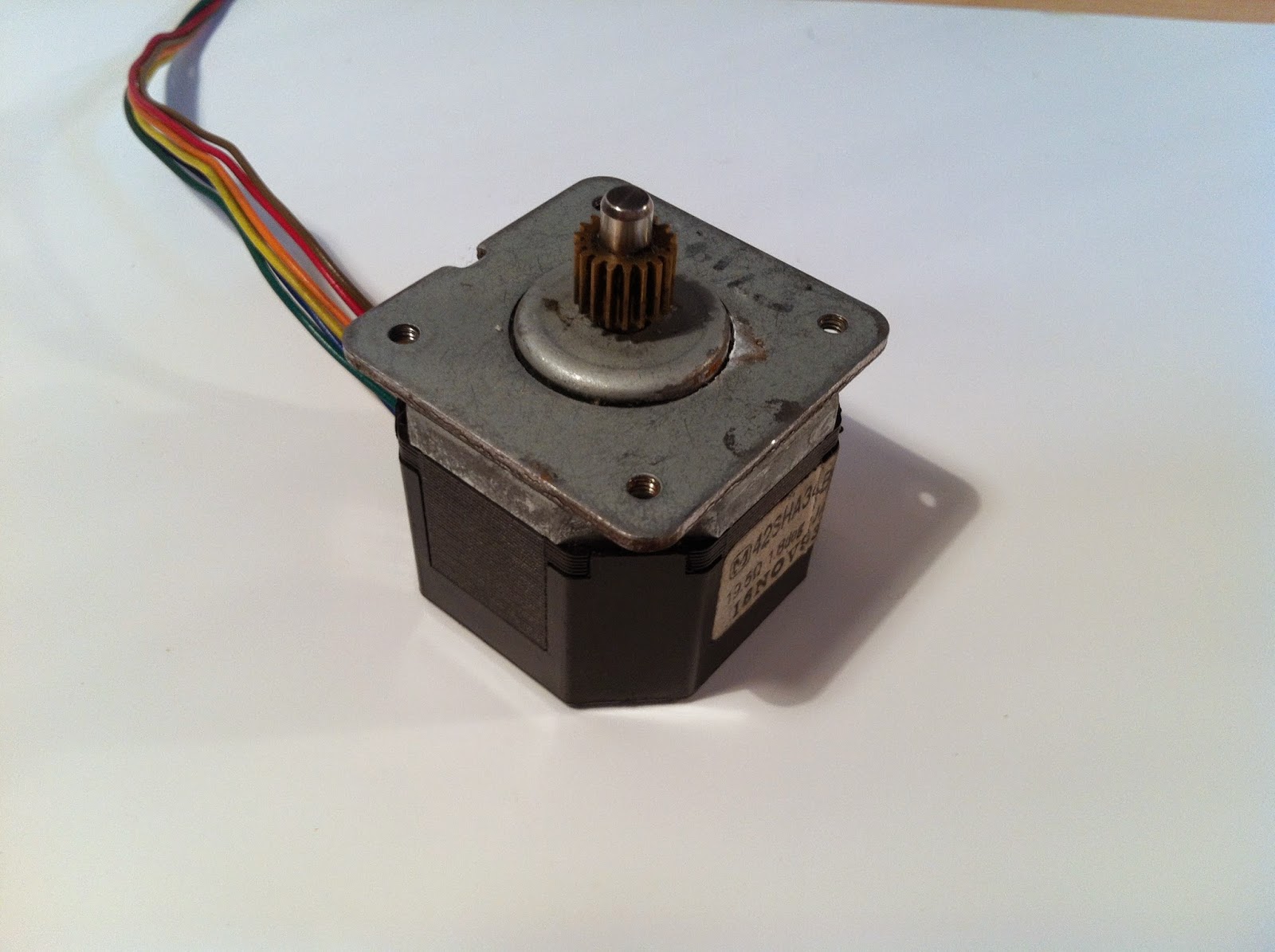 |
| it is a 6 wires stepper but I use it as a 4 wires one |
You can drive a stepper in several ways, in fact there are 2 mains configurations (UNIPOLAR and BIPOLAR) and 4 mains sub-configurations (full step 1 phase on, full step 2 phases on, half stepping and micro stepping). The possible configurations varies upon the type of stepper used, if you choose a 4 wires stepper you can only drive it in the bipolar configuration, else if the stepper has 6 wires you can choose between the unipolar or bipolar configuration, if the stepper has 8 wires it's a bit more tricky so i prefer to avoid this particular topic, anyway you can use an 8 wires stepper as a 6 or 4 wires one, check the possible connections below (I'm using the "6 leads bipolar series connection"):

If you don't know the internal connections of your stepper or you don't know how to identify the correct leads to use I recommend to read this guide.
With the stepper that I'm using the leads configuration is:
Every configuration has his own pro and cons, check it here (the unipolar configuration is not treated).
With the stepper that I'm using the leads configuration is:
 |
| Connections' detail of my 6 wires stepper used as a 4 wires one |
I'm planning to use the BIPOLAR FULL STEP 2 PHASE ON configuration, this will squeezes out the maximum torque possible from the stepper because I need it to move the cutter mounted on the machine.
In a future post I will release some Firmware written in a simil-Basic programming language, in particular this language is used to program the PIC PICAXE which I'm using to drive the steppers, but for now I'm not going to dive any more on this topic.
I've bought my stepper at a fair, it is used and quite old (seems that it has been built in 1993) but it was really cheap (only 4€), it works and for now it's enough just to write down some firmware.
I don't know exactly what voltage is needed by this stepper, in fact doesn't exist any datasheet for this model and there aren't any useful informations printed on the plate, anyway I'm driving it with 12V in this way, with a coil resistance of 39Ω (19.5Ω from the ends of each coil/phase to its own center tap, 39Ω if you leave unconnected the center tap), it draws approximately 300mA (12V/39Ω) for each phase (2 phases, 600mA in total) which i provide through 4 BC337-25 (NPN) and 4 BC328-40 (PNP) transistors in a H-bridge configuration.
I've roughly measured the torque generated by my stepper, its holding torque is about 0.7kg/cm (at 30rpm) which, compared to other similar stepper, is quite ridiculous. This can be due to the fact that is old and because has been used in the past, anyway I'm not gonna use this particular stepper for the final product, this is just a prototype.
In the next post I'll discuss more about the driving configurations and the wiring of the steppers.
Thanks, I'm actually working on a new post about etching PCBs!
ReplyDelete