29 January 2017
18 June 2015
PHP cookies based unique hit counter (side project)
In this post I'll show you a simple implementation of an unique hit counter that can be used wherever you need to.
This counter is cookies based, so obviously if the visitors of your blog/website disables the cookies in their browser this script will not work as expected, in fact if the cookies are disabled the script can no longer know if the actual user has been already counted or not, for this reason there are other implementations that rely on the user IP, anyway, personally I think that for an hit counter a cookies based solution is good enough.
Now I'll explain how the script works, but first let's take a look at the code:
As you can see from the code above the script prints the visits number that has been read from the website database, than it creates a cookie named "visited" and, if the user hasn't already this cookie, gives it to the user and updates the visits number in the database. If the user will visit this page again before the expiration date of the cookie his visit will not be counted because the script will update the visits number only if the user hasn't the cookie named "visited".
You can find the source code for the hit counter in the download section of the blog.
This counter is cookies based, so obviously if the visitors of your blog/website disables the cookies in their browser this script will not work as expected, in fact if the cookies are disabled the script can no longer know if the actual user has been already counted or not, for this reason there are other implementations that rely on the user IP, anyway, personally I think that for an hit counter a cookies based solution is good enough.
Now I'll explain how the script works, but first let's take a look at the code:
 |
| Hit counter source code opened with Geany |
You can find the source code for the hit counter in the download section of the blog.
19 May 2015
Design and build a CNC machine
Building the Base:
In the past two weeks I was designing and building the CNC's base and the X carriage.
I started from designing the entire CNC machine with SketchUp (you can find the 3D model in the downloads section of the blog), then I went to a local metal shop to buy some iron flat bars, after that I started to punch every hole onto the bars, according to the 3D model, with a center punch and finally I've drilled and tapped each hole.
Here the photos of the iron flat bars:
 |
| Iron flat section bars before tracing |
 |
| The stepper holder after tracing and punching (I've used a black marker to enhance the visibility of the traces) |
With this kind of construction the bars haven't to be perfectly cut to lenght (for example if the bars are roughly cut with a band saw), in fact the distance from the holes will not be affected from that, moreover the nuts and bolts construction allow you to achieve the maximum precision and squareness possible when assembling the machine, even without ultra precision tools.
For the nuts I suggest the nylon lock ones as they prevents misalignment over time.
The tools needed are:
For the nuts I suggest the nylon lock ones as they prevents misalignment over time.
The tools needed are:
- A drill press (even a cheapy chinese one, the important is to tune it up correctly);
- Some drill bits;
- Some metal taps (preferably a three pieces set);
- A metal vise;
- A center punch;
- A metal scriber;
- Some lub oil (I suggest WD-40);
 |
| My drill press, note the threaded rod, it prevents the drill's table from twisting under load |
 |
| Drilling the base's holes, I've clamped multiple bars at once to quicken the process |

 |
| I've noticed that this kind of coupler creates tons of backlash, so later on it will be replaced with something else |

When I was designing the CNC I decided to make every hole 1mm bigger to allow some adjustment when assembling, and this works great, especially if you haven't been much accurate at tracing/punching.
For the rails I've used C40 steel round bars, note that painting the rails isn't a good idea, in fact the paint will not last very long due to the continous rubbing of the bearing over the bar, so to prevent rust you should keep the bars always oiled, WD-40 works great.
For the rails I've used C40 steel round bars, note that painting the rails isn't a good idea, in fact the paint will not last very long due to the continous rubbing of the bearing over the bar, so to prevent rust you should keep the bars always oiled, WD-40 works great.
Building the X Carriage:
For the X carriage I've used the same approach that I've used to build the base, here the result:


When assembling make sure to be ultra accurate at squaring up everything, especially the base's bars, the X carriage's bars and the rails. Remeber that if two pieces are dead on square and you place them in front of a light source you shouldn't be able to see the light between the pieces and the square.
29 April 2015
Design and build a CNC machine
The logic driver:
Over the last few weeks I was developing the logic driver for the CNC machine, with logic driver I mean that circuit that converts the step and direction inputs coming from the parallel port of the PC to a predefined 4 bit pattern that drives the power driver, and that consecutively drives the steppers.
The pattern that I'm referring to is the following:
 |
| Drive mode: Bipolar Full stepping two phases on |
The circuit has been developed as a FSM (finited states machine), I've started designing it by writing down the ASM diagram, then I've extrapolated the circuit's truth table from the diagram, next from the truth table I've extracted the logic formulas and finally from the formulas I've drawn the actual circuit, here it is:
 |
| On the left a 2 bit up/down counter, on the right 2 XOR gates and a NOT gate |
As you can see the circuit is very simple to implement, on the 4 output (on the right) will be attached the 4 wires of the power driver, that consists simply of an L298N dual full H bridge chip plus some flyback diodes and other miscellaneus parts, as you can see in the following image:
I've bought 3 of those power driver board on ebay for 3€ (3.3$) each from china.
The original idea was to build the power driver too with mosfets, but that approach is way more expensive than buy the already built driver.
Here the image of a dual full H bridge implemented using mosfets and flyback diodes: |
| Theese two circuits are used to drive one single stepper, one for each phase of the stepper |
To build the logic driver I'm using the HCF4029BE 4 bits up/down counter, the CD4070BE quad 2 inputs XOR gates and a 2N3904 transistor used as a NOT gate.
I chosen theese parts because they're quite cheap and easy to find online.
Let's talk a little bit about resetting the counter, I've came up with a neat idea (then I discovered that this method is used in almost all modern microcontrollers), it consists of auto resetting the chip for some milliseconds after the power is turned on, this is accomplished with a RC delay line and an op. amp. used in the inverted Schmitt trigger non symmetrical configuration, here an example:
 |
| The output J1 is connected to the reset pin of the counter (the HCF4029BE reset pin is active high) |
Here an image of one logic driver mounted on the breadboard:

The breakout board:
The logic driver is only one of the parts that mades up the CNC breakout board, in fact the breakout board is made up by the parallel port, the logic driver, the power driver, the auto reset circuit, the e-stop (with its own de-bounce circuit), the coolant controller, the spindle controller and so on.
I want to keep the design of my CNC simple, so the unnecessary functions are left off, such as the PWM spindle speed control, the home and limit switches, etc...
Here an image of the breakout board schematic:
 |
| As you can see the auto reset circuit can be also used as a switch de-bounce circuit |
You can find the EAGLE schematics for this breakout board in the download section of the blog.
04 March 2015
Jungle (side project)
Jungle is a small file manager app that I've developed some years ago, finally today, after some months, has been published on the Ubuntu Software Center.
The program is quite minimalistic, it offers 5 functions, such as: "move", "copy", "delete", "open" and "search".
Jungle can be used with every type of file because it launches the right program to use depending on the file selected, it can be very usefull if you are using a lightweight desktop environment such as LXDE or OPENBOX.
The program is written in Python, I've used the TkInter graphics libraries for the GUI, it can run on both x86 and x64 machines, unfortunately it isn't cross platform due to the implementation choices that I made quite some time ago.
If you're interested check it out by yourself, you'll just need to search for "Jungle" in the Ubuntu Software Center.
The program is quite minimalistic, it offers 5 functions, such as: "move", "copy", "delete", "open" and "search".
 |
| Screenshot of Jungle running on Ubuntu 13.10 64 bit |
Jungle can be used with every type of file because it launches the right program to use depending on the file selected, it can be very usefull if you are using a lightweight desktop environment such as LXDE or OPENBOX.
The program is written in Python, I've used the TkInter graphics libraries for the GUI, it can run on both x86 and x64 machines, unfortunately it isn't cross platform due to the implementation choices that I made quite some time ago.
If you're interested check it out by yourself, you'll just need to search for "Jungle" in the Ubuntu Software Center.
21 January 2015
My Components' DB (side project)
MCDB is a program that I've developed in the last month and an half, it has born due to the fact that I needed some sort of database where I could have stored all of my electronic components in order to easily keep trace of what I had available in stock. Another thing that led me to develop this program has been the need to find my components quickly, in fact my component boxes are very messy and in order to find if something was available or not I had to spend a lot of time.

* Only Wheezy-backports or newer distributions are supported on Debian.
 |
| Screenshot of MCDB running on Windows 8.1 64 bit |
The program is written in C++, for the user interface I've used the Qt graphics library.
The entire project is Open Source, cross platform and distributed for free, you can look at the source code here.
At the moment the supported operating systems are Windows (all versions) 32/64 bit, Linux (all versions *) 32/64 bit and Mac OS X 10.10 Yosemite.
If you're interested you can visit the program's page on SourceForge by clicking here, or you can directly download the program by clicking on the link below.
* Only Wheezy-backports or newer distributions are supported on Debian.
28 December 2014
Design and build a CNC machine
The stepper motor:
An important choice in CNC machines' design is the appropriate motor to use, at the moment I'm designing a small milling machine and I plan to use steppers type NEMA 17 for it, you can find their datasheet here.
For now I'm using this stepper:
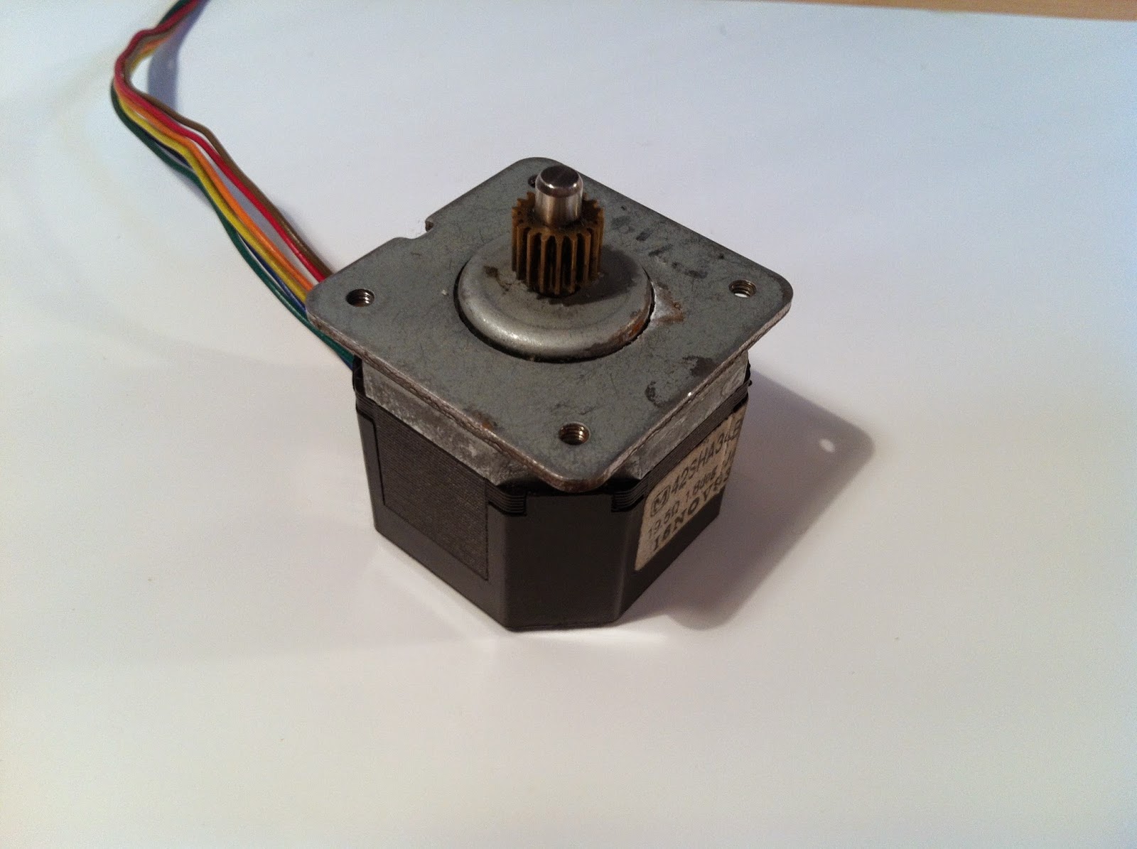 |
| it is a 6 wires stepper but I use it as a 4 wires one |
You can drive a stepper in several ways, in fact there are 2 mains configurations (UNIPOLAR and BIPOLAR) and 4 mains sub-configurations (full step 1 phase on, full step 2 phases on, half stepping and micro stepping). The possible configurations varies upon the type of stepper used, if you choose a 4 wires stepper you can only drive it in the bipolar configuration, else if the stepper has 6 wires you can choose between the unipolar or bipolar configuration, if the stepper has 8 wires it's a bit more tricky so i prefer to avoid this particular topic, anyway you can use an 8 wires stepper as a 6 or 4 wires one, check the possible connections below (I'm using the "6 leads bipolar series connection"):

If you don't know the internal connections of your stepper or you don't know how to identify the correct leads to use I recommend to read this guide.
With the stepper that I'm using the leads configuration is:
Every configuration has his own pro and cons, check it here (the unipolar configuration is not treated).
With the stepper that I'm using the leads configuration is:
 |
| Connections' detail of my 6 wires stepper used as a 4 wires one |
I'm planning to use the BIPOLAR FULL STEP 2 PHASE ON configuration, this will squeezes out the maximum torque possible from the stepper because I need it to move the cutter mounted on the machine.
In a future post I will release some Firmware written in a simil-Basic programming language, in particular this language is used to program the PIC PICAXE which I'm using to drive the steppers, but for now I'm not going to dive any more on this topic.
I've bought my stepper at a fair, it is used and quite old (seems that it has been built in 1993) but it was really cheap (only 4€), it works and for now it's enough just to write down some firmware.
I don't know exactly what voltage is needed by this stepper, in fact doesn't exist any datasheet for this model and there aren't any useful informations printed on the plate, anyway I'm driving it with 12V in this way, with a coil resistance of 39Ω (19.5Ω from the ends of each coil/phase to its own center tap, 39Ω if you leave unconnected the center tap), it draws approximately 300mA (12V/39Ω) for each phase (2 phases, 600mA in total) which i provide through 4 BC337-25 (NPN) and 4 BC328-40 (PNP) transistors in a H-bridge configuration.
I've roughly measured the torque generated by my stepper, its holding torque is about 0.7kg/cm (at 30rpm) which, compared to other similar stepper, is quite ridiculous. This can be due to the fact that is old and because has been used in the past, anyway I'm not gonna use this particular stepper for the final product, this is just a prototype.
In the next post I'll discuss more about the driving configurations and the wiring of the steppers.
Subscribe to:
Comments (Atom)